Readers who found hi3d while troubleshooting a GLB to STL conversion will learn why a model may appear tiny, sideways, or unprintable, and which checks to make before slicing.
An STL that looks wrong in the slicer does not necessarily have a broken mesh. I check size and orientation first, then inspect the geometry for problems that conversion cannot fix.
The short version
- Tiny or huge? GLB uses meters; slicers normally interpret STL numbers as millimeters. Check the converter’s output dimensions before downloading.
- Sideways? GLB is Y-up, while printing workflows expect Z-up. Keep the printing rotation on unless the source was oriented unusually.
- Missing walls or failed slices? Conversion preserves geometry; it does not turn an open surface into a closed solid.
- Still unsure? Diagnose those issues in that order. Changing scale will not close a hole, and mesh repair will not correct a unit mistake.
Start with the dimensions, not the slicer
When a model opens as a speck, it is tempting to drag its scale control until it looks printable. I would check the source units first. The GLB to STL converter shows the output size in millimeters before download and applies the meter-to-millimeter conversion that a printing workflow needs.
A GLB follows the glTF convention: its units are meters. STL stores triangles but no unit declaration. Slicers generally treat the numbers in an STL as millimeters. If a converter simply copies the coordinates, a figurine that is 0.25 m tall in the GLB arrives as a 0.25 mm object. Converting meters to millimeters makes it 250 mm tall instead. The shape did not change; the interpretation of its coordinates did.
That standard is a starting assumption, not proof that the artist followed it. A file can be saved as GLB even if its author modeled as though the numbers meant centimeters. That is why the output dimensions matter more than the filename. Decide how tall the physical object should be, then compare that target with the size shown in the converter.
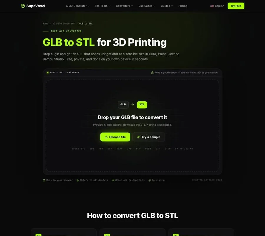
The GLB to STL page shows the intended output dimensions before you download the file.
Fix a tiny or giant STL
Use the size preview to make a deliberate correction rather than compensating blindly in the slicer.
- Open the original GLB and read its output size. If the dimensions match your intended print in millimeters, leave the unit setting alone. If a model appears implausibly large or small, do not assume its visible shape tells you which unit the author used.
- Correct the source-unit assumption if necessary. The converter starts from glTF’s meter convention. If the file was actually authored in centimeters, change File units to cm and watch the displayed output size update. Use the size, not a guess about where the file came from, to judge the result.
- Set the actual print size. If the displayed model is too large for the bed, enter a factor in Scale. The panel also offers Scale to 100 mm tall when its size warning appears. Use that shortcut only if 100 mm is the height you want; otherwise, choose your own target.
- Download and verify in the slicer. Press Convert to STL and check the imported dimensions before arranging supports or choosing a layer height. If they disagree with the converter’s preview, inspect the slicer’s import settings rather than repeatedly rescaling the geometry.
Size affects more than whether the object fits. A slender feature that looks substantial on screen can become too thin to print once the whole model is reduced. Get the overall dimensions right before deciding that a missing detail is a mesh error.
Fix a model lying on its side
Scale can be correct while the model still arrives in the wrong pose. GLB uses Y-up; slicers and printing tools conventionally use Z-up. Copying coordinates without accounting for that difference can put a standing character on its back.
Keep Z-up for printing switched on in the converter. It is the default: the model is rotated 90 degrees, centered, and placed with its lowest point at z = 0. That addresses the coordinate-system mismatch without asking the slicer to guess what “up” meant in the source file.
Then look at the model itself. An artist may have saved an object lying down, or built its scene with an unconventional orientation. The default axis conversion cannot know that the intended standing pose differs from the file’s pose. If the preview still looks wrong, compare it with the source and rotate the object deliberately in your modeling tool or slicer. Do not keep changing File units to solve an orientation problem; units alter size, not which surface should face the build plate.
Also distinguish “on the bed” from “stable on the bed.” Placing the lowest point at z = 0 does not guarantee a broad contact area. Check the slicer preview for a sensible first layer before printing.
Check which glTF file you actually have
A .glb is a single-file form of glTF, but some downloads instead provide a .gltf alongside a separate .bin containing the geometry. If that is what you received, use the glTF to STL converter rather than treating the .gltf as a GLB. For a separate-file download, select the .gltf and .bin together, or supply them in a .zip.
The same print checks apply: inspect the millimeter output size, keep Z-up enabled, and verify the result in the slicer. Texture images can be left out when the destination is STL, but the separate .bin cannot; without it, the converter has no geometry to write.
This distinction also explains a common disappointment. Both kinds of glTF can carry materials and textures, but STL cannot store them. A painted seam or logo that existed only as an image will not become raised geometry during conversion. Inspect the actual mesh if that detail matters to the print.
When the size and pose are right but slicing fails
A converter can write every visible mesh into an STL and still leave you with something unprintable. Screen models often use surfaces that only need to look solid from the camera’s viewpoint. A single-sided leaf or hair card has no physical wall thickness. Separate pieces may appear attached in a viewer while barely touching—or not touching at all.
First, inspect the converted mesh, including wireframe where useful. Look for paper-thin planes, gaps, floating pieces, and areas that disappear in the slicer’s layer preview. Then use STL repair if the slicer reports open or non-manifold edges. Its health report identifies holes, open edges, non-manifold edges, flipped faces, and separate shells, with problem edges marked in red.
An open edge belongs to only one triangle, leaving a gap in the surface. A non-manifold edge is shared by three or more triangles, making the boundary between inside and outside ambiguous. A slicer needs that boundary to decide where to make walls and infill. Repair can close holes and correct face direction; compare its before-and-after report before downloading the result.
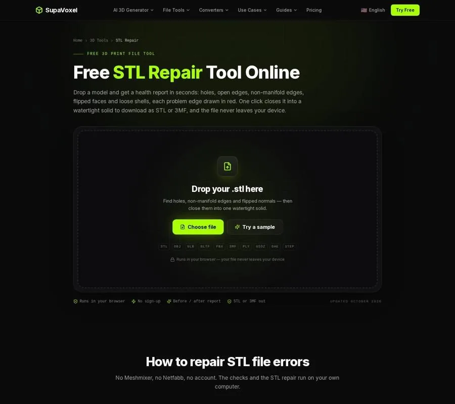
The STL repair page marks problem edges and reports whether the repaired mesh is watertight.
Know what repair will not do. It does not thicken a 0.2 mm wall, so that wall may still vanish with a 0.4 mm nozzle. It also does not turn a painted texture into printable detail. Its default floating-piece removal deletes loose shells smaller than 1% of the model’s triangles; turn that option off if small, separate parts are intentional. If a large section of the source is missing, a generated patch is only a guess at its shape. That calls for editing the model, not accepting a closed file on faith.
Do not use the reverse conversion as a repair
If your goal changes from printing to displaying a print model on the web or in AR, the direction of the unit conversion changes too. The STL to GLB converter turns millimeter-sized STL geometry into meter-sized GLB geometry and changes Z-up to Y-up. Its size preview is in meters: a 120 mm object should read 0.12 m.
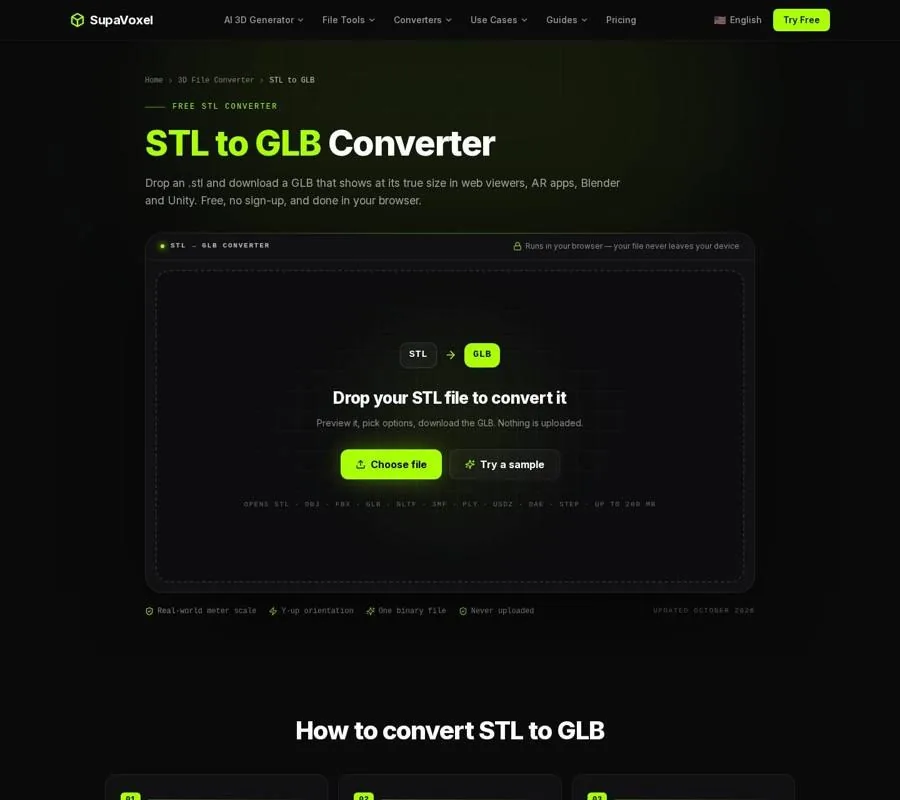
The STL to GLB page previews dimensions in meters for the resulting GLB.
That reverse trip is useful for presentation, not for recovering anything lost on the way to STL. STL contains no textures, UVs, or original material colors, so converting it back produces a neutral gray material rather than restoring the source GLB’s appearance. Keep the original GLB if you need its screen-ready version. Keep the checked STL for slicing.
FAQ
Why is my converted STL tiny even though the GLB looked normal?
The GLB’s coordinates may have been copied without converting meters to millimeters, or the source may have been authored using a different unit convention. Check the converter’s output size and adjust File units or Scale before downloading.
Will converting a GLB to STL make it watertight?
No. Conversion carries the visible mesh geometry across; it does not close every opening or give single-sided surfaces thickness. Check the slicer preview and repair reported mesh errors separately.
Why did the colors disappear?
STL does not store textures or material colors. The converted file contains geometry for printing, not the GLB’s visual materials.